

Spray Column Manufacturer Expertise for Efficient Industrial Processes
2026-08-21
Efficient industrial processes depend on more than smart control systems—they rely on equipment that performs consistently under real-world conditions. Spray columns are exactly that kind of equipment, and the gap between adequate and exceptional often comes down to the manufacturer’s expertise. Sinou brings that depth of know-how to every unit, turning design intent into reliable, long-term process performance.
Why Spray Tower Performance Hinges on Nozzle Placement
A spray tower can look flawless on paper—right diameter, enough height, proper gas velocity—yet still deliver poor absorption or drying efficiency if the nozzles are not positioned with intent. Nozzle placement dictates how evenly the liquid droplets are distributed across the tower's cross-section. When nozzles sit too close to the walls, a significant portion of the spray hits the inner surface, creating wet zones that lead to buildup, corrosion, and uneven gas-liquid contact. Conversely, placing them too far apart leaves dry corridors where gas slips through untreated, drastically reducing overall performance.
The vertical location of nozzles matters just as much as their horizontal spacing. If a nozzle is mounted too high, droplets may coalesce or evaporate before they reach the reaction zone, weakening the intended mass transfer. Too low, and the liquid doesn't have enough residence time to interact with the rising gas stream. Skilled engineers often use computational fluid dynamics to map droplet trajectories and avoid overlapping spray cones that cause localized flooding. The goal is a balanced mist that fills the tower volume without excessive wall wetting or internal recirculation.
Another overlooked factor is the nozzle angle relative to the gas flow. Upward-facing nozzles in a counter-current tower can create back-mixing and pressure drops, while downward-facing ones may be carried too quickly by the gas. Even the nozzle type—hollow cone, full cone, or flat fan—changes the placement strategy. Operators who treat nozzle positioning as a set-and-forget detail often spend more on chemical additives, reheating, or maintenance to compensate for poor liquid distribution. In contrast, a placement tuned to the specific gas load and liquid properties routinely cuts energy use and improves capture efficiency by double digits.
Balancing Pressure Drop and Contact Time in Column Design
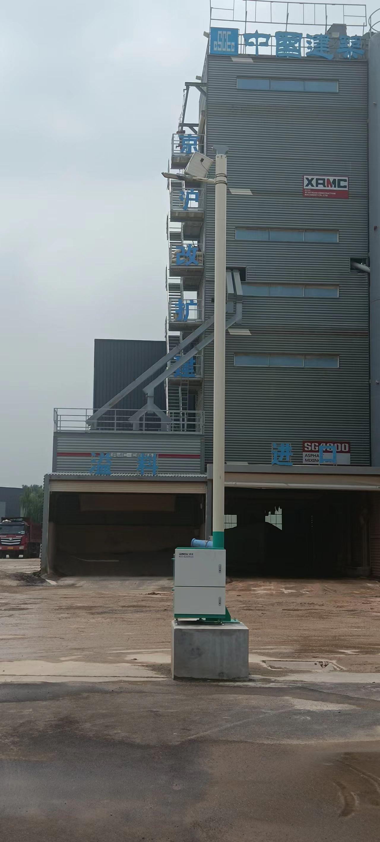
A common misstep in column design is treating pressure drop and contact time as independent variables. In practice, reducing particle size or packing density to sharpen breakthrough curves inevitably raises the frictional resistance across the bed. The designer must recognize that every gain in separation efficiency via longer residence time comes with an energy penalty, and ignoring this coupling leads to columns that are either hydraulically impractical or economically unviable.
One effective way to approach the trade-off is to map both parameters against superficial velocity and bed length. For a given target resolution, a taller column with larger particles can offer the same contact time as a shorter column with smaller particles, but the pressure drop behavior diverges sharply. The Kozeny-Carman relationship shows that halving the mean particle diameter multiplies pressure drop by roughly fourfold, while doubling the bed length only doubles it. This nonlinearity means that modest adjustments to particle size often outweigh changes in column geometry, a fact easily overlooked in early-stage sizing.
Some modern designs break the classic trade-off by using structured packings, segmented beds, or tapered flow distributors. These elements allow more uniform residence time distribution without incurring the pressure penalties of fine random packings. Iterative modeling combined with pilot-scale runs remains the most reliable path, because purely analytic shortcuts tend to overestimate ideal contact time and underestimate maldistribution effects. The goal is not to eliminate pressure drop but to keep it at a level where the improved mass transfer justifies the pumping cost.
Material Choices That Extend Service Life in Harsh Streams
Selecting the right materials for components exposed to fast-moving, debris-laden water is rarely about finding the strongest option on paper. It is more often about matching hardness, toughness, and corrosion resistance to the specific wear mechanisms at play. In many upland rivers, pumps, impellers, and pipe bends fail not because they lack tensile strength, but because they cannot absorb repeated impacts from sand and gravel without cracking or eroding away.
Austenitic manganese steel, for instance, work-hardens under repeated battering, forming a tough surface skin while the core remains ductile enough to resist fracture. Ceramic-lined piping offers a different path: the ceramic layer takes the abrasion, while the steel shell carries structural loads. Neither approach is universally superior; the choice depends on whether the stream carries mostly fine silt, sharp gravel, or larger cobbles, and whether maintenance crews can easily replace worn sections or need a set-and-forget solution.
Beyond metallurgy, elastomers and polymers such as polyurethane and UHMWPE often outperform rigid materials in high-velocity slurry because they deflect slightly under particle impact and then recover, dissipating energy that would otherwise gouge a harder surface. Pairing these materials with proper joint design and regular inspection points can stretch replacement intervals well beyond what standard carbon steel achieves in the same stream conditions.
Accuracy in Fabrication: Tolerances That Matter
A tolerance on a print is never just a number. When a part calls for ±0.005 inches on a bore, the real challenge isn’t the math—it’s holding that size after the tool heats up, the coolant shifts, and the fixture relaxes. Shops that take tolerances seriously will map out thermal drift on long runs, swap inserts before they dull, and measure in the same setup whenever possible. Without that kind of attention, a tight spec is just wishful thinking.
Not every dimension deserves the same level of fuss. A bearing seat might need tenths-level accuracy, while a clearance hole can wander a few thousandths without consequences. Good fabricators read the print with an eye for function: where does this surface mate, where does load transfer, and where does a mismatch actually cause problems? That conversation with the design intent matters more than blindly chasing the tightest numbers.
Verification is where accuracy either holds up or falls apart. It’s not enough to measure once and hope the rest of the batch follows. Checking fixtures, CMM programs, and in-process gauging all have to agree with each other, and they all need to be checked against a known standard. The best shops treat tolerance not as a final inspection hurdle but as a repeatable process—something you can prove on part one, part fifty, and the last piece off the machine.
Retrofitting Existing Columns for Higher Throughput
Retrofitting an existing column for higher throughput rarely means swapping in a completely new stationary phase. Often the fastest gains come from re-evaluating the column hardware and the surrounding fluid path. Upgrading end fittings to low-dispersion designs, shortening connection tubing, and reducing internal diameters where possible can shave critical seconds off each run without altering the separation chemistry. For labs already running standard 4.6 mm ID columns, moving to a 3.0 mm or even 2.1 mm format with the same packing material can cut solvent consumption by up to 80% while maintaining resolution, provided the system can handle the higher backpressure and smaller injection volumes.
Another practical route involves shortening the column length or changing the particle size within the same bonded phase family. Going from 5 µm to 3 µm or sub-2 µm particles on a shorter bed delivers similar plate counts at significantly reduced analysis times. If the existing column housing is compatible, repacking with a smaller particle size is often cheaper than buying a new column and avoids requalification of a different hardware platform. Pay attention to frit porosity; older frits designed for 5 µm particles may not retain 1.7 µm material reliably, so upgrading the frits alongside the packing is a small but critical step.
Temperature is a frequently overlooked retrofit lever. Raising the column oven set point from ambient to 40–60 °C lowers mobile phase viscosity, allowing higher flow rates without exceeding pump pressure limits. This simple adjustment can cut run times by 20–30% for many reversed-phase methods, with only minor selectivity shifts that are easily compensated by a slight reduction in organic modifier. Before committing to any retrofit, baseline the current method’s peak capacity and retention time reproducibility so that the impact of each hardware or operational change can be quantified rather than guessed at.
New Approaches to Mist Elimination and Carryover Control
Recent developments in mist elimination have shifted away from relying solely on traditional wire mesh pads and vane packs. These older technologies, while effective under steady conditions, often struggle with varying droplet sizes, high liquid loads, or the presence of viscous aerosols. Newer designs incorporate hybrid structures that combine fine fiber layers with open drainage channels, allowing for both high capture efficiency and rapid liquid removal. Field tests in chemical processing plants show that these hybrid systems can reduce downstream carryover by more than forty percent compared to conventional pads, especially during process upsets.
Carryover control has also benefited from computational fluid dynamics used during the design phase. Instead of guessing how gas and liquid phases will interact inside a separator, engineers now simulate droplet trajectories across a wide range of operating conditions. This approach helps identify dead zones where mist tends to accumulate and re-entrain, and it guides the placement of demisting stages for better performance. One notable application involved a refinery scrubber where a redesigned inlet distributor and a staged coalescer arrangement cut amine losses to less than ten parts per million by volume.
Another emerging trend is the use of oleophobic and superhydrophobic surface treatments on demister elements. These coatings prevent liquid films from wetting the fiber surfaces, which reduces the pressure drop and delays the onset of flooding. In a recent trial at a natural gas dehydration unit, coated mesh pads maintained stable operation for twice as long as uncoated ones before requiring washdown. Such surface engineering, combined with modular cassette designs that simplify retrofitting, gives operators a practical way to upgrade older vessels without major shutdowns or capital expenditure.
FAQ
Look for evidence of in-house engineering rather than just assembly. A capable manufacturer can walk you through design calculations for gas-liquid contact, pressure drop, and droplet size distribution, and they typically keep records from past installations. Ask about their testing rigs and whether they can run pilot trials with your actual process fluid.
It changes everything from maintenance intervals to process stability. For acidic or chloride-heavy streams, a manufacturer with real expertise will specify materials like fiberglass-reinforced plastic, duplex stainless steel, or lined carbon steel instead of defaulting to 316 stainless. They should also explain how thermal expansion and chemical attack at nozzle areas influence long-term reliability.
Because the nozzles control droplet size, spray angle, and distribution uniformity. A manufacturer focused on efficiency will help you balance fine atomization for mass transfer against the risk of clogging or excessive entrainment. They often offer adjustable nozzle headers or interchangeable tips so the same column can handle different throughputs without a full redesign.
Beyond standard hydrostatic tests, look for spray pattern imaging, airflow or gas distribution checks, and leak testing under vacuum or positive pressure. Some manufacturers run a water simulation with dye tracers to show liquid coverage across the column cross-section. This kind of pre-shipment validation catches uneven wetting that would hurt efficiency later.
Yes, but it depends on the manufacturer's experience with those conditions. For high temperatures, expect expansion joints, heat-resistant packing or internals, and careful selection of elastomers. For high-solids or slurry streams, the design should include larger free passage nozzles, sloped bottoms, and easy access for flushing. Request examples of similar installations to confirm they have actually built equipment for those duties.
Several ways: optimizing the liquid-to-gas ratio to avoid over-pumping, using low-pressure-drop mist eliminators, and designing the column geometry to minimize recirculation zones. Some manufacturers also offer variable frequency drives on pumps or fans so the system can ramp down during reduced load, which cuts operating costs without sacrificing treatment performance.
A reliable manufacturer will provide installation supervision, commissioning assistance, and operator training. They should also keep detailed fabrication drawings and material certificates on file, so replacement internals or nozzles can be supplied years later without guesswork. Ask whether they offer performance audits or field service visits to troubleshoot changes in pressure drop or efficiency.
The decision depends on your gas flow, liquid loading, and what you need to remove. Spray columns work well when you want low pressure drop, can handle fouling or sticky particulates, and need simple internals. A competent manufacturer will compare your required removal efficiency, turndown, and liquid chemistry against packed bed or venturi options rather than pushing one technology for every application.
Conclusion
The performance of a spray column often comes down to how well the nozzles are placed. A manufacturer with real experience understands that even slight misalignment or uneven spray patterns can create dead zones and reduce mass transfer. Getting the distribution right means looking at the entire column, not just the spray header, and adjusting nozzle type, angle, and elevation to match the gas flow profile. At the same time, the design has to balance pressure drop against the contact time needed for absorption or scrubbing. Too much pressure drop wastes energy, while too little contact time leaves contaminants in the gas stream. Experienced fabricators use computational fluid dynamics and pilot testing to find that balance, then translate it into practical column geometry. Material selection is another area where expertise pays off. In harsh streams containing acids, chlorides, or abrasive particulates, the wrong alloy or lining can fail within months. A skilled manufacturer guides the choice of corrosion-resistant alloys, thermoplastics, or dual-laminate construction to extend service life without over-engineering the cost.
Fabrication accuracy is often underestimated. Tolerances on nozzle support rings, downcomer clearances, and shell roundness directly affect how evenly liquid and gas distribute. A manufacturer that holds tight tolerances, verified by laser alignment or full-scale mock-ups, prevents the kind of preferential channeling that quietly saps efficiency. When an existing column needs higher throughput, retrofitting is rarely as simple as adding more spray nozzles. It calls for careful evaluation of the existing shell, internals, and mist elimination capacity. A knowledgeable partner can redesign the spray header, adjust the liquid-to-gas ratio, and add high-efficiency mist eliminators or new coalescing media to cut carryover without a complete rebuild. New approaches to mist elimination, such as advanced vane packs with drainage channels or fiber-bed mist eliminators with hydrophobic treatment, have made it possible to push columns harder while keeping downstream equipment clean. Combining these improvements with better nozzle placement and material choices turns an ordinary spray column into a high-efficiency, reliable part of an industrial process.
Contact Us
Contact Person: HaiYan
Email: [email protected]
Tel/WhatsApp: +86 18957325588
Website: https://www.senyoubeton.com/