

HV Switchgear Manufacturer Powering Reliability in High-Voltage Applications
2026-09-10
In the world of high-voltage power distribution, reliability isn't a feature—it's the entire game. A single point of failure can cascade into hours of downtime, safety risks, and costly repairs. That's why the choice of an HV switchgear manufacturer matters more than most engineers admit. At Chang Song, we've spent years not just building switchgear, but dissecting every failure mode until our designs hold up under conditions that would humble lesser equipment. This article unpacks what separates a genuinely dependable HV switchgear supplier from the crowd—and why our approach keeps critical infrastructure running when the pressure peaks.
Where Dielectric Stress Meets Its Match
Dielectric stress rarely announces itself with a flash. It accumulates quietly along insulation boundaries, through micro-voids, and around sharp conductor edges, slowly eroding the material's ability to hold back voltage. The moment of failure is usually abrupt, but the path to it is methodical and predictable once you know where to look.
What makes this challenge interesting is not the stress itself, but the material's response to it. Some dielectrics resist by spreading the field evenly, others by absorbing partial discharge energy without forming carbonized channels. The real breakthrough comes when you stop treating dielectric stress as an external force and start designing materials that adapt to it, redistributing electric fields before they concentrate into destructive hot spots.
That shift in thinking changes everything. Instead of thicker barriers or conservative derating, you get tailored composites whose molecular structure actively mitigates stress gradients. It is less about withstanding a static threat and more about removing the conditions that let that threat become lethal in the first place.
Fault Current Ratings We Prove, Not Just Print
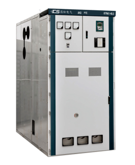
Many manufacturers list fault current ratings straight from calculation sheets. We take a different route. Every rating we publish gets pushed through actual short-circuit tests in certified high-current labs, with fault currents applied at worst-case X/R ratios and full rated voltage. That means real copper bars glowing, real enclosures taking the mechanical stress, and real breakers opening under fault—not a simulation.
During testing we monitor temperature rise, let-through current, and mechanical deformation at multiple points. A 100 kAIC rating isn't just a label; it's a device that has survived repeated bolted faults, been inspected for contact wear and insulation integrity, and then re-tested to confirm it still clears safely. If a design can't hold its rating in the lab, we don't ship it.
This changes what you can expect in the field. When a downstream fault happens, the difference between a printed rating and a proven one shows up as equipment that stays intact, bus bars that don't twist, and protection that trips within its published time. We'd rather spend the money on test cells and destruction reports than another glossy datasheet claim.
From Single-Line Diagram to Type-Tested Assembly
Taking a single-line diagram and turning it into a type-tested assembly is rarely a straight copy job. The diagram shows the functional intent—where breakers sit, how busbars link, what feeds what—but it says almost nothing about busbar bending radii, heat dissipation inside an enclosure, or the exact arrangement needed to pass a short-circuit test. Engineers who do this work learn to read between the lines: a symbol on paper might imply three different physical layouts, each with different temperature rise profiles and clearance requirements.
The real skill is in mapping that schematic logic onto a verified, standardized construction. You pick a frame size, split the busbar runs, check the derating for grouped devices, and then confirm against the assembly's certified test data. It is not about reinventing the panel every time; it is about fitting the project's one-line into a proven envelope without violating the type test boundaries.
What often gets overlooked is how much hidden negotiation happens between the diagram's simplicity and the assembly's physical constraints. Maybe the incoming breaker needs a wider compartment than the standard cubicle offers, or the cable entry at the bottom conflicts with a horizontal busbar. Resolving those tensions—while keeping the final result still recognizable as a type-tested assembly—is where experienced designers earn their keep.
Grid Code Compliance Without the Usual Rework
Meeting grid code requirements often turns into a frustrating loop of simulation mismatches, late-stage control tuning, and expensive hardware swaps. The typical culprit is treating compliance as a final checkbox rather than a design constraint from day one. By shifting the focus to early electrical and control co-design, teams can align inverter response, protection settings, and fault ride-through behaviour with the specific grid codes of the target market before procurement begins.
A more reliable approach uses a verified model library that matches the actual hardware behaviour, not generic approximations. Running pre-compliance studies against real grid code profiles—such as low voltage ride-through curves, reactive power capability, and frequency response requirements—exposes weak points while changes are still inexpensive. This model-based verification reduces the need for repeated type tests and lets engineers explore edge cases like weak grid conditions or phase jumps without waiting for a physical prototype.
The result is fewer design iterations, shorter certification timelines, and a smoother path from prototype to grid connection. Instead of discovering a non-compliance issue during factory acceptance testing, the system arrives with parameter sets already validated for the intended grid environment. That practical, front-loaded strategy eliminates the usual rework and keeps project schedules intact.
Partial Discharge Signatures We Actually Listen To
Every insulation flaw has its own acoustic fingerprint. A sharp, intermittent crackle often points to surface tracking or corona activity near a conductor, while the deeper, rhythmic buzz of internal void discharge carries a different diagnostic weight. We don't just capture waveforms; we learn the dialect of failing insulation, separating harmless background hum from the subtle pre-failure chatter that tends to go unnoticed in routine testing.
Listening to partial discharge is less about chasing a single number and more about reading context. The amplitude tells you something is happening, but the repetition rate, phase position, and tonal quality tell you where and why. A random, popcorn-like burst under rising voltage suggests one failure mechanism, while a steady, phase-locked hiss points to another entirely. Our field recordings become a reference library, letting us match today's signature against decades of known failure modes.
What surprises most newcomers is how clearly the equipment speaks once you tune your ear. A healthy bushing is almost silent; a degrading cable termination starts to whisper long before it shouts. We use that early whisper to schedule downtime on our terms, not on the failure's. That shift, from reactive repair to informed listening, is what separates a maintenance routine from an actual reliability strategy.
Lifecycle Support That Outlasts the Punch List
A punch list signals the end of construction, but it shouldn't signal the end of our involvement. Once the final walkthrough is signed, we keep a direct line open for questions about equipment sequences, warranty registrations, and seasonal adjustments. That means if a system behaves oddly during the first winter or a controls setting needs rebalancing in July, you're not chasing down subcontractors on your own.
This phase is less about formal deliverables and more about being a built-in resource. We track long-lead warranties, local code updates that affect your building type, and maintenance intervals that tend to slip through the cracks after occupancy. Our team keeps site-specific notes on what was installed where, so a callback three years later doesn't start from zero.
The goal is simple: your facility should perform as intended long after the last item is crossed off. We stay reachable for minor fixes, replacement part guidance, and planning future capital improvements. It's support shaped around how the building actually operates, not a binder that gets shelved and forgotten.
FAQ
It comes down to rigorous design validation and real-world testing. A trustworthy manufacturer uses busbar materials with high conductivity and low thermal expansion, performs partial discharge and temperature rise tests on every configuration, and validates short-circuit withstand capability through independent labs. They also maintain traceability of every batch of insulating components and offer field service teams that can respond within hours, not days.
Utility substations, heavy industrial plants, renewable energy collector stations, and data center feeds are prime examples. Each has different stress patterns: solar farms deal with frequent switching and harmonics, mining operations face dust and vibration, while offshore wind requires corrosion-resistant enclosures and compact gas-insulated layouts. Off-the-shelf designs often fail in these uneven conditions.
They rely on type testing beyond minimum standards. That includes lightning impulse withstand, power frequency overvoltage, and internal arc fault containment. Many add partial discharge screening at multiple stages of assembly, not just final test. For gas-insulated units, leak rate verification and moisture control in SF6 or clean air are non-negotiable. The goal is to eliminate weak points before commissioning.
No two substation layouts or grid codes are identical. Customization can mean adjusting busbar orientation to fit an existing building, integrating protection relays that communicate with a specific SCADA protocol, or changing enclosure ratings for coastal salt spray. A manufacturer that only sells fixed catalogs forces the project to adapt, which often creates expensive civil work or compromises maintainability.
Infrared thermography on joints and cable terminations every 12 to 18 months catches loose connections early. Contact resistance testing of circuit breaker poles and disconnectors reveals pitting or misalignment. For gas-insulated switchgear, continuous density monitoring of SF6 or clean air is essential. Mechanical operators should be exercised periodically, even in standby duty, to prevent grease hardening and linkage seizure.
Yes, but the approach matters. Non-intrusive sensors for temperature, partial discharge, and gas pressure can be retrofitted without disturbing primary insulation. Digital outputs should use hardened protocols like IEC 61850 with redundant communication paths. The key is designing the monitoring system to fail silent and local, never taking the protection or interlocking functions offline. Cybersecurity segmentation between operational and monitoring networks is also mandatory.
IEC 62271 defines most international type tests, including internal arc classification and mechanical endurance. In North America, IEEE C37 series and ANSI ratings are common. For specific environments, check IEC 60068 for environmental testing and IEC 61869 for instrument transformers. Buyers should ask for complete type test reports from accredited third-party labs, not just certificates of conformity.
Conclusion
When insulation systems face steep voltage gradients and contaminated environments, we treat dielectric stress as an engineering problem with numerical answers—not a hope. Our busbar and enclosure geometries are shaped by finite element analysis, then confirmed through impulse and power-frequency withstand tests. Fault current ratings are not nominal claims; every assembly is short-circuit tested at accredited labs, and we publish the oscillograms, not just the nameplate. Projects move from a rough single-line diagram to a fully type-tested assembly without losing design intent: we lock mechanical clearances, CT ratios, and interlocking logic early, so the panel you approve is the panel that gets built. Grid code compliance is handled during the design review stage, not as a late-stage retrofit. Protection settings, arc-resistant construction, and auxiliary trip circuits are matched to the utility's requirements before steel is cut, eliminating the usual rework loops.
Partial discharge is read as a diagnostic language, not background noise. We attach UHF and TEV sensors to critical joints and use pattern recognition to distinguish harmless corona from dangerous voids, so insulation defects are caught long before they become outages. After commissioning, lifecycle support continues past the punch list: we maintain a living document of recommended spare parts, offer breaker timing and contact resistance checks, and keep a direct line to the engineers who designed your switchgear—not a call center. Reliability in high-voltage applications, for us, means one continuous responsibility from dielectric design to end-of-life refurbishment.
Contact Us
Contact Person: Tonglun Chen
Email: [email protected]
Tel/WhatsApp: 8618906642555
Website: https://www.cncsele.com