

Busbar Insulator OEM: A Comprehensive Guide to Custom Manufacturing
2026-09-10
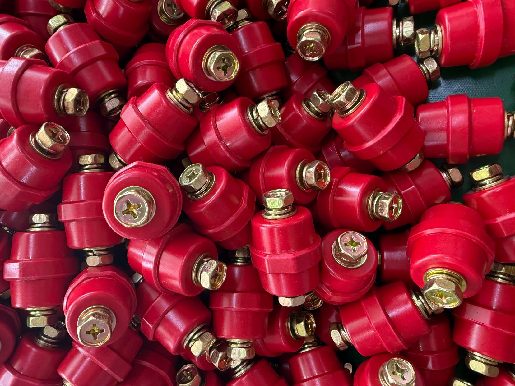
Busbar insulators may look like simple components, but their fit, material behavior, and creepage distance determine whether a power distribution system stays safe under load. Standard catalog parts rarely match your specific busbar layout or environmental demands. That’s why custom OEM manufacturing is worth a closer look. In this guide, we break down the key decisions behind busbar insulator OEM projects—covering design inputs, molding processes, testing requirements, and cost drivers—drawing on practical experience from MOLDVOLT.
When Off-the-Shelf Busbar Insulators Can't Handle Your Load Profile
Standard busbar insulators are designed around typical operating conditions, but many industrial environments push electrical systems far beyond those assumptions. When your load profile includes frequent high-current spikes, harmonic distortion, or prolonged overload periods, molded off-the-shelf insulators may develop microcracks, surface tracking, or thermal stress that goes unnoticed until a fault occurs. Unlike catalog parts, a tailored insulator solution accounts for the actual thermal cycling, mechanical vibration, and ambient contamination your busbars face daily.
Load profiles with steep di/dt transients or continuous duty near the equipment rating create localized heating at the insulator contact points. This weakens the polymer matrix, accelerates creepage path erosion, and can lead to partial discharge that erodes insulation integrity over time. Off-the-shelf options rarely specify endurance under such irregular stress, leaving you with premature replacements or unexpected downtime. Custom-engineered insulators, on the other hand, can incorporate reinforced sheds, deeper creepage distances, and materials matched to your specific harmonic and thermal signature.
The real risk shows up when your busbar system runs close to its rated capacity while ambient temperatures fluctuate widely. Standard insulators may pass a one-time short-circuit test but fail after months of thermomechanical fatigue. If you are seeing tracking marks, discoloration near the mounting points, or nuisance flashovers, that is a clear sign your load profile demands more than a generic part. A properly specified insulator should reflect how your system actually behaves—not just the nameplate values printed on a datasheet.
What Actually Happens Between First Sketch and First Article
Between the first sketch and the first article, things rarely follow the neat path you'd expect. The sketch might look coherent on paper, but the moment you start translating those lines into a pattern, every assumption gets tested. Seam allowances shift, proportions that seemed fine at one scale suddenly feel off at full size, and the fabric you imagined behaves nothing like the sketch suggests. You end up making a series of muslin toiles—sometimes five or six—just to see where the silhouette collapses or where the drape fights the construction.
Then there's the quiet part nobody talks about: the back-and-forth with the patternmaker or the factory sample room. You send over a flat pattern with notes scribbled in the margins, and what comes back is a first proto that's 80% right but that last 20% is everything—shoulder pitch, collar roll, pocket placement. Each revision means another sample, another round of waiting, another set of tweaks. It's not wasted time; it's where the design actually earns its structure.
By the time the first article lands on your table, it looks almost nothing like the original sketch in the ways that matter. The overall idea survives, but the details have been through the wringer. Hems got adjusted, closures moved, linings swapped. That's the real work between the first sketch and the first article: a series of small, stubborn corrections that turn a two-dimensional idea into something you can actually put on a body.
Resin Chemistry Beyond the Datasheet for Thermal Cycles
Datasheets give you the headline numbers—glass transition temperature, coefficient of thermal expansion, maybe a vague mention of “thermal stability.” But real thermal cycling is a slow-motion war fought at the molecular level, and the spec sheet rarely tells you who’s winning. The resin chemistry that survives a thousand cycles isn’t just about high Tg or low CTE; it’s about how the crosslink network breathes, how dangling chains rearrange under repeated stress, and whether the formulation was tuned for fracture toughness rather than just heat deflection. When you push a board from -40°C to 150°C dozens of times a day, the failure rarely starts where the datasheet predicts.
One of the least discussed factors is the role of free volume and how it evolves with each thermal excursion. Most epoxy systems don’t return to the same volumetric state after the first few cycles—they densify, and that densification changes the local stress landscape around every copper via and glass fiber bundle. A resin that looks stiff and stable on paper might be accumulating microcracks at the resin-fiber interface simply because its free volume collapse outpaces the reinforcement’s ability to accommodate it. Blends that incorporate flexible aliphatic segments or carefully chosen toughening agents often outperform “high-performance” aromatic systems in cyclic testing, not because they’re stronger, but because they absorb and redistribute strain more evenly.
Then there’s the question of moisture. Even a few tenths of a percent of absorbed water can act as a plasticizer during thermal cycling, lowering the effective Tg just enough to shift the failure mode from brittle fracture to ductile creep—or vice versa. Datasheets almost never account for the combined effect of humidity and thermal shock, yet that’s the real-world condition for automotive underhood electronics or outdoor telecom gear. Designing for thermal cycles means looking at the resin’s hydrophobic character, its post-cure conversion rate, and whether the formulation leaves behind unreacted hardener that can migrate and embrittle over time. The best resin chemistry isn’t the one with the highest Tg on page one; it’s the one that keeps its mechanical identity intact after ten thousand cycles of being pulled in every direction at once.
Creepage, Clearance, and the Space You Forgot to Leave
When a board runs at high voltage, two numbers jump onto the spec sheet: creepage and clearance. Clearance is the straight-line distance through air between two conductive parts; creepage is the path along a surface. Most designers read the table, add ten percent for safety, and move on. But there's a third gap that never appears in the standards — the physical room your components need to actually sit there.
You can nail the clearance requirement on paper and still end up with a capacitor body pressed against a heatsink, or a screw terminal whose plastic lip hangs over the isolation barrier. That forgotten space isn't just about arcing. It's about tolerance stack-up, solder fillet spread, and the way a board flexes when it gets warm. The standard says you need 3.2 mm. Reality says the connector's anchor tab extends 0.8 mm past the footprint outline, and now your 3.2 mm is 2.2 mm with a slight tilt.
The fix isn't hard, but it asks for a habit change. Draw the isolation boundary first, not last. Then place components with their real, measured extents — including the solder mask opening, the glue dot, the pick-and-place margin. If two parts face each other across that boundary, add the worst-case mechanical offset to the electrical number. It's not overdesign; it's the gap between the drawing and the physical board. Once you start leaving that space on purpose, the arcing problems stop being mysterious.
Why Partial Discharge Testing Catches What Visual Inspection Misses
A clean junction box, dry cable terminations, and no scorch marks on a panel can easily pass a close visual check. Yet that same equipment may be hiding gas-filled voids inside epoxy insulation or hairline cracks that only widen under thermal cycling. These defects do not announce themselves on the surface until breakdown is already underway, which is exactly why surface-level inspections give a false sense of security.
Partial discharge testing listens for the tiny electrical pulses that occur when a void, delamination, or contamination site briefly ionizes under high voltage. Because each discharge leaves a measurable high-frequency signature, the test can locate weak spots long before they grow into a flashover or a short circuit. This makes it possible to find a failing splice inside a switchgear cubicle or a degraded bushing deep inside a transformer without opening every cover or waiting for visible smoke and carbon tracking.
In practice, crews that combine routine visual checks with periodic partial discharge sweeps catch failures months earlier than visual-only programs. An insulation defect that would have shown up as a charred contact or melted cable jacket becomes instead a work order with a clear location and severity reading. That difference keeps unplanned outages off the board and spares maintenance teams from chasing intermittent faults that leave no visible trace.
Questions Smart Buyers Ask Before Commissioning a Custom Run
Before signing off on a custom run, the sharpest buyers dig into the practical realities that glossy sales sheets never mention. They want to know exactly what happens if a component fails mid-production, how the factory handles scrap rates above the agreed threshold, and whether the line will pause for spot inspections or only at the end. It’s not about distrust; it’s about understanding the levers you can pull when something inevitably drifts from the spec.
Another line of questioning revolves around the little details that quietly balloon into budget overruns. Who pays for the trial batch that doesn’t quite match the approved sample? What are the real lead times for specialty materials, not just the optimistic estimates? Smart buyers also ask to see the actual run schedule and the names of the operators who will handle the job — because a custom run is only as reliable as the people and processes behind it.
Finally, they lock down the post-production terms before the first unit comes off the line. That means confirming how overruns or underruns are priced, what documentation accompanies the shipment for traceability, and how the factory stores or disposes of leftover custom components. These may sound unglamorous, but they’re the difference between a smooth partnership and a costly, finger-pointing mess later.
FAQ
It covers everything from initial design consultation and material selection to mold fabrication, prototyping, testing, and volume production. The manufacturer works from your drawings or 3D models to produce insulators that meet your exact mechanical and electrical specifications, often including custom mounting holes, creepage distances, and surface finishes.
The choice depends on voltage class, environmental exposure, and mechanical load. Epoxy resin compounds are popular for indoor medium-voltage applications due to good dielectric strength and dimensional stability. For outdoor or high-pollution environments, cycloaliphatic epoxy or silicone rubber offer better tracking resistance and hydrophobicity. Ceramic and glass-reinforced polyester are also used where high rigidity or cost is a priority.
Usually it starts with a technical review of your drawings or CAD files, followed by a feasibility assessment. Then the OEM partner designs the mold and produces a small batch of prototypes. After you approve the prototypes and any required type tests, production tooling is finalized and volume manufacturing begins. Each batch undergoes routine testing before packing and shipment.
Critical parameters include operating voltage, required creepage and clearance distances, mechanical bending and tensile strength, ambient temperature range, UV exposure, and any chemical or pollution conditions. Mounting configuration and available space also dictate the overall shape and insert type. Standards compliance, such as IEC or ANSI, should be clarified early to avoid redesign.
Look for ISO 9001 certification and experience with electrical insulation testing. The manufacturer should perform routine tests like power-frequency withstand voltage, partial discharge measurement, and mechanical load tests on every production batch. Material traceability, in-process dimensional checks, and documented non-conformance handling are also signs of a mature quality system.
Request a detailed first article inspection report that includes dimensional measurements (ideally with CMM or 3D scanning) and material certificates. Before mass production, you should approve pre-production samples and agree on acceptance criteria. Reputable OEM partners also provide batch test reports and allow third-party inspection if needed.
Prototype tooling and samples often take 3 to 6 weeks, depending on complexity. After sample approval, volume production typically runs 4 to 10 weeks, but this can stretch if special materials or additional testing are required. Clear communication on order quantity and urgent deadlines helps the manufacturer plan capacity.
Standard parts rarely fit every switchgear layout or busbar arrangement. Custom OEM manufacturing lets you optimize creepage distance, reduce space, integrate mounting features, and match your brand or assembly process. It also ensures consistent performance under your specific operating conditions, which off-the-shelf products may not guarantee.
Conclusion
Standard busbar insulators often fail when load profiles push beyond their rated thermal or mechanical limits, leaving engineers with cracked housings, tracking paths, or clearance violations that no catalog part can resolve. That moment usually triggers a custom OEM conversation—but the real work starts well before tooling is cut. Between the first sketch and first article, a competent manufacturer will map out field conditions, define failure modes, and run finite element or thermal cycling simulations on candidate geometries. Resin chemistry gets teased apart far beyond a one-page datasheet: glass transition temperature, filler loading, and cure schedule all shift how a part behaves after hundreds of thermal cycles. A resin that looks fine at room temperature can turn brittle or lose creep resistance once the busbar expands and contracts under load. Without this level of scrutiny, you end up paying for a custom shape that still fails in service.
Space planning is where many custom insulator designs quietly go wrong. Creepage and clearance values on paper don't account for real assembly tolerances, bolt heads, busbar edges, or the gap you forgot to leave for installation. A design that meets IEC or UL minimums in CAD may still flash over after dust settles or humidity rises. That's why partial discharge testing matters more than a final visual check—corona activity inside voids or along interfaces starts invisibly and degrades insulation long before any crack or burn mark appears. Smart buyers ask pointed questions before commissioning a run: What filler system will you use and why? How do you validate first articles under thermal shock? Will you pulse-test every production lot or only sample? Can you share data on creepage under polluted conditions? The answers separate a vendor who just molds parts from a partner who understands how a busbar insulator actually survives.
Contact Us
Contact Person: Hellen
Email: [email protected]
Tel/WhatsApp: 86-13634205622
Website: https://www.voltcabinet.com