

Bespoke Hard-Seal Ball Valve Manufacturer for Critical Industrial Applications
2026-08-17
In critical industrial applications, a valve is only as good as its seal under real-world stress—extreme temperatures, abrasive media, and relentless pressure cycles. Off-the-shelf hard-seal ball valves often fall short when specifications get tight. That’s where a truly bespoke manufacturer like ZMV comes in. Instead of forcing your process to fit a standard design, ZMV engineers hard-seal ball valves around your exact operating conditions, material compatibility, and leakage requirements. This article takes a closer look at why custom-engineered sealing solutions matter when failure isn’t an option—and what sets ZMV apart in the field.
When Soft Seats Fail: Hard-Seal Ball Valve Design for Abrasive and High-Temperature Service
Soft-seated ball valves often fail in abrasive or high-temperature duties long before the rest of the valve shows wear. Polytetrafluoroethylene (PTFE) and other polymer seats begin to soften around 200°C, lose dimensional stability, and extrude into the flow path. Abrasive particles then embed in the seat, scoring the ball and creating leak paths that a simple spring or increased torque cannot correct.
Hard-seal designs replace the soft insert with a metal or ceramic seat ring, typically faced with Stellite, tungsten carbide, or chromium carbide. The ball and seat are lapped as a matched pair to achieve a tight shutoff without relying on polymer deformation. A bellows or disc spring behind the seat absorbs thermal expansion and maintains contact pressure as the valve cycles from cold start-up to full operating temperature.
Material expansion rates must be balanced carefully: a 300-series stainless seat in a carbon steel body will loosen at high temperature, while a solid tungsten carbide seat can crack under thermal shock. Many successful designs use a hardfaced seat on a more ductile base, combined with a scraper lip or self-cleaning geometry to prevent particle build-up on the sealing surface. In mining slurries, catalyst handling, and superheated steam, these valves outlast soft-seated alternatives by a factor of five or more.
Custom Ball and Seat Profiles That Match Your Actual Media, Not a Generic Trim Chart
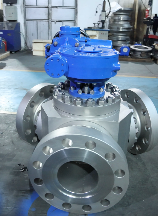
A generic trim chart assumes every fluid behaves like water, but real process media never do. Slurries carry abrasive particles that chew up standard seat profiles, viscous polymers refuse to release a flat ball surface cleanly, and hot hydrocarbons with dissolved gases can flash across a trimmed seat and erode it within weeks. That is why we machine the ball and seat geometry directly from your actual media sample—measuring viscosity under shear, particle size distribution, and corrosion behavior under operating pressure. No more guessing between a "general purpose" and a "slurry" trim from a catalog row.
The result is a matched pair where the ball's leading edge breaks the fluid film without trapping solids, and the seat's lip compresses just enough to seal without cold flow or extrusion. For a chemical plant pumping crystallizing salts, we opened the seat angle by seven degrees and added a downstream relief groove to prevent scale locking the ball. In another case, a food processor's tomato paste needed a wider contact band and a softer durometer to avoid pulping seeds into the seal. These adjustments come from testing your media, not from a generic recommendation chart.
Over time, that specificity pays off in fewer unplanned shutdowns and less trim inventory. One refinery cut seat replacement frequency from every six weeks to over a year after switching to a profile shaped for their high-sulfur crude blend. Because the ball and seat are no longer over-trimmed to compensate for unknown conditions, you also avoid the excess pressure drop and actuator torque that generic "heavy duty" trims force on every valve. Your actual media defines the profile—exactly as it should.
Hardfacing and Coatings That Turn Standard Bodies into Erosion-Resistant Workhorses
When a standard steel housing meets a high-velocity slurry stream, it rarely lasts through the first season. Hardfacing changes that calculus by depositing a sacrificial armor layer directly onto the worn surface. Rather than replacing the entire component, maintenance crews can rebuild the worn geometry and then cap it with a wear-resistant alloy that often outlasts the original base metal several times over.
The real art lies in matching the coating to the specific wear mechanism. Sliding abrasion from wet sand calls for high-chromium carbide deposits, while impact-heavy applications like crusher hammers benefit from manganese or tungsten carbide blends. Thermal spray and laser cladding add precision where dimensional control matters, creating dense, well-bonded layers that preserve tight tolerances. This isn't a one-size-fits-all shop trick; it's a materials selection problem solved case by case.
The payoff shows up in reduced downtime and fewer spare parts sitting on the shelf. A pump casing that once needed replacing every few months can run for years after a well-chosen hardfacing treatment. For operators in mining, dredging, or heavy agriculture, that difference converts directly into lower cost per ton moved and a more predictable maintenance schedule. It's a practical upgrade that keeps standard bodies working far beyond their original design limits.
Zero-Leakage Testing That Mirrors Your Plant's Pressure Swings and Thermal Cycles
Leak testing in a real plant never happens under steady conditions. Pressures ramp, hold, drop, and spike while temperatures climb during a batch and fall during a shutdown. Most test rigs ignore this, running a single static check that misses the leaks which only open when a flange cools or a seal relaxes under cyclic load. Our approach reproduces those swings: we program the exact pressure profile and thermal ramp from your process historian, then run the component through repeated cycles until the leak behavior stabilizes. That way a fitting that passes a bench test at room temperature but weeps at 180°C gets caught before it reaches your pipe rack.
The test sequence can be as simple as a daily start-stop transient or as complex as a multi-step batch with holds at intermediate pressures. We measure leakage not as a single pass/fail number but as a rate curve over time and temperature, so you can see whether a gasket recovers after a thermal excursion or progressively loses sealing force. This matters for sites handling light hydrocarbons, heat transfer fluids, or steam condensate, where tiny emissions accumulate into reportable quantities. By matching the duty cycle rather than testing to a generic standard, we often find that components which meet a 10⁻³ mbar·L/s spec on paper fail within a few hours of realistic cycling.
For maintenance and reliability teams, the output is a direct comparison: your plant's actual pressure-temperature envelope overlaid with the measured leak response. No more guessing whether a valve will hold after a weekend cool-down or whether a newly torqued joint will relax after the first thermal cycle. The data supports replacement decisions, torque revisions, and seal material changes without waiting for a costly unplanned shutdown.
Direct Engineering Collaboration from P&ID Markups to Final Torque Verification
Early design reviews often reveal discrepancies between piping and instrumentation diagrams and the actual torque requirements of critical flanged connections. By bringing field engineers, process designers, and maintenance leads into the same markup session, those gaps get closed before they become expensive rework items. A marked-up P&ID with torque values scribbled next to each joint isn't just a note—it's a working agreement on how the system should be assembled and verified.
That agreement carries through to the torque verification stage, where the same annotated drawings serve as the baseline for wrench selection, bolt tightening sequences, and final documentation. Teams that treat the markup as a live document rather than a static record can trace every decision from the initial redline to the last measured click of the torque wrench. This continuity reduces the guesswork that typically creeps in when different groups interpret the same specification independently.
The result is fewer unexpected leak paths, shorter commissioning delays, and a clearer audit trail when questions arise months later. Instead of relying on generic torque tables or tribal knowledge, everyone works from a single source that has been refined through direct collaboration. That kind of alignment doesn't happen by accident—it comes from deliberately linking the markup process to the final mechanical check.
Long Service Life in Refining, Chemical, and Power Generation Without Constant Rebuilds
Refineries, chemical plants, and power stations punish equipment with corrosive fluids, thermal cycling, and relentless pressure swings. Many operators accept frequent teardowns as unavoidable, but that mindset quietly drains budgets and erodes uptime. A better approach starts with materials and design choices that resist the specific damage mechanisms present in each unit — from chloride stress corrosion in exchangers to creep in high-temperature reactor circuits.
Long service life comes from details like solid-solution nickel alloys, controlled ferrite in welds, and thermal spray coatings that keep erosion at bay. Precision machining and post-weld heat treatment remove residual stresses that turn minor flaws into forced outages. For example, steam turbine casings with upgraded bolting and improved steam path geometry routinely run multiple years between major inspections, even under sliding pressure operation.
The payoff shows up in fewer crane lifts, less scaffolding, and longer intervals between turnarounds. Instead of rebuilding the same pump or valve every cycle, crews handle only condition-based replacements. That shifts maintenance from emergency response to planned, low-risk work. Operators get stable throughput, predictable costs, and assets that hold alignment and efficiency far longer than standard equipment.
FAQ
Instead of forcing your process to fit a standard valve, we start with your operating conditions—pressure cycling, temperature swings, abrasive media, and line size—and design the body, ball, seats, and stem around them. The result is a valve that drops into your system without adapters, compromises, or unexpected wear patterns.
You'll find them in chemical processing, oil and gas, power generation, mining, and pharmaceutical manufacturing—anywhere a leak or failure isn't an option. The common thread is severe service: high pressure, high temperature, corrosive or erosive flow, and tight shutoff requirements.
Yes, and we don't just swap the seat material. We review the thermal expansion of the ball and body, the stem sealing under thermal cycling, and the seating force at full differential pressure. Materials like tungsten carbide, Stellite, or ceramic are selected based on the specific temperature range and media.
Depends on the service. Tungsten carbide gives excellent erosion resistance for slurries and catalysts. Stellite works well for high-temperature scaling. Ceramic suits highly corrosive or ultra-pure streams. We'll recommend a pairing of ball and seat materials rather than a one-size-fits-all hard coating.
The seat geometry and preload are engineered together. We don't rely on soft deformation to seal. Instead, the ball and seat are lapped as a matched set and the seat is spring- or pressure-energized to maintain contact as surfaces wear. Prototype testing includes cycle counts with periodic leakage checks, not just a single bench test.
Full material traceability, pressure test reports, welding procedure records, and dimensional inspection sheets are standard. If you need API 607/6FA fire-safe, ISO 15848 fugitive emission, PED, or SIL-rated documentation, we produce those before shipment. No chasing paperwork later.
It depends on the complexity and current shop load, but generally 8 to 14 weeks from drawing approval to shipment. Rush orders are possible when a shutdown is at risk, but we'd rather plan ahead and get the design review right than rush a critical valve.
Conclusion
Soft-seated valves start to leak, wedge, or wash out long before their rated service intervals when abrasive slurries, catalyst fines, or superheated steam become part of the daily routine. Instead of forcing a catalog product into that duty, a bespoke hard-seal ball valve builder reworks the trim around the actual media. Ball and seat profiles are cut to match particle size, viscosity, and thermal expansion data from your process, not lifted from a generic trim chart. Hardfacing alloys and ceramic or tungsten carbide coatings are then applied only where erosion actually occurs, turning a standard forged body into a workhorse that shrugs off wire drawing and seat galling. The result is a valve that holds its torque signature and shutoff class after months of throttling, not just after a bench test.
Acceptance testing moves beyond a single bubble-tight check. The valve is cycled under pressure swings and thermal ramps that mirror your plant's startup and upset conditions, so stem seal relaxation and seat distortion show up before installation, not after. Engineering support runs from marked-up P&IDs through final torque verification, with the manufacturer's own machinists and metallurgists on the same drawing revisions as your reliability team. That direct loop shortens the time between a failed soft seat and a running replacement. In refining, chemical, and power generation services where a rebuild crew on standby is no longer acceptable, this approach stretches mean time between repairs well past typical soft-seated designs, cutting both planned outages and the unplanned kind.
Contact Us
Contact Person: Lucas Lin
Email: [email protected]
Tel/WhatsApp: +8613968913000 / +8613868610141
Website: https://www.zhengmaogroup.com