

400kW Diesel Generator Manufacturing: Key Steps and Quality Control Insights
2026-09-10
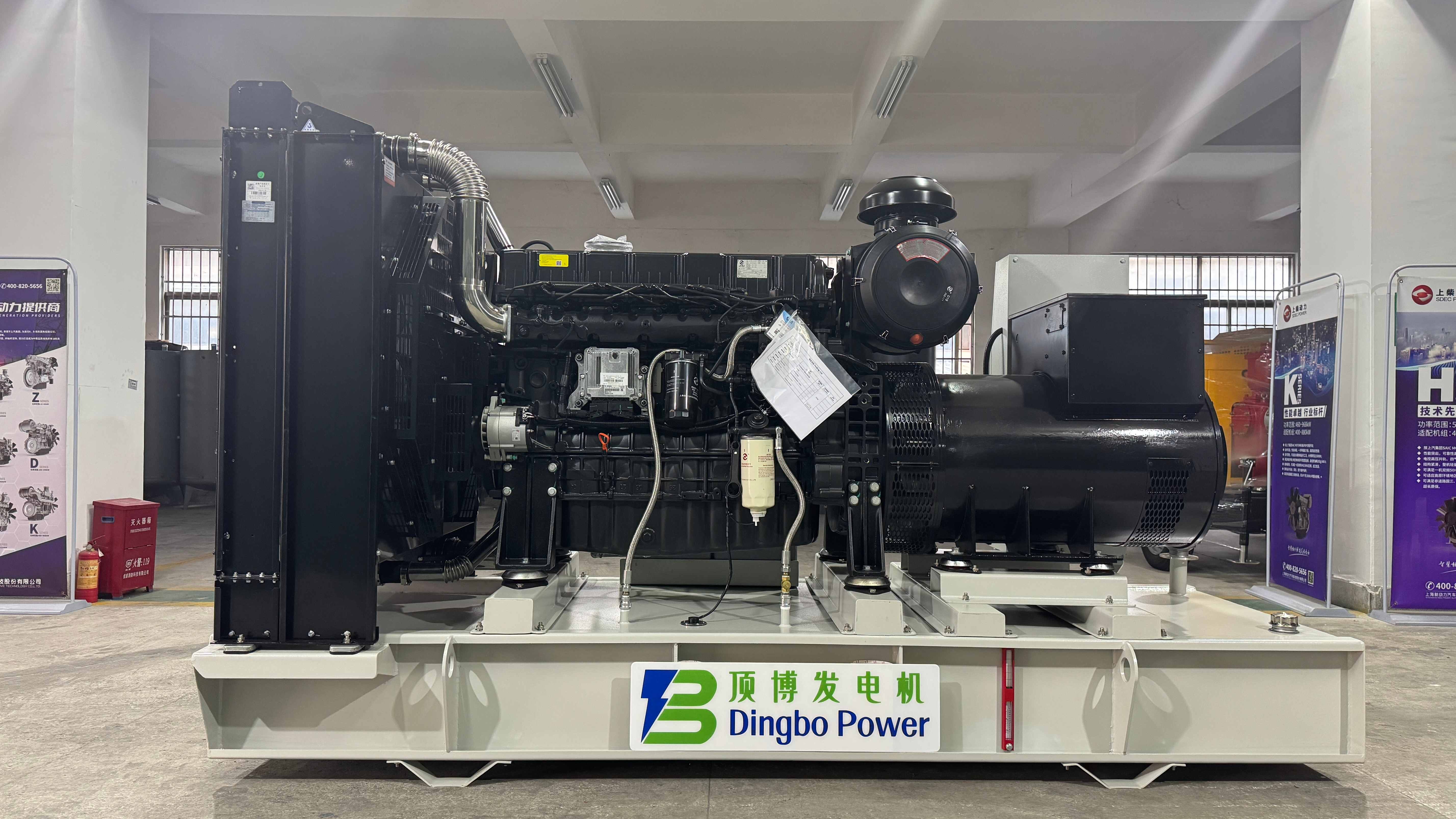
Ask anyone who has managed a construction site or a remote facility: a 400kW diesel generator is not just a purchase—it’s a bet on uptime. What most buyers never see is the chain of decisions behind the casing: how the engine block is machined, how the alternator is wound, and how many test hours the unit logs before it ever reaches a pallet. This post walks through the manufacturing steps and quality control checks that genuinely determine whether a 400kW set will hold up. You’ll also find out why DINGBO POWER treats certain factory routines as non-negotiable rather than optional.
From Casting to Honing: Where Block Integrity Is Decided
A raw casting looks solid, but the decisions that determine whether a block will hold up under load happen long before the first cut. In the foundry, cooling rates and alloy composition set the grain structure, while core placement and mold filling control wall thickness and the absence of trapped porosity. A block that passes visual inspection can still carry internal stress or thin spots that only show up once cylinder pressures and thermal cycles start working on it.
Machining steps like boring and decking add another layer of risk. Aggressive tool pressure or poor fixture alignment can pull a casting out of spec even if the iron or aluminum was perfect. Then honing arrives with a more subtle job: it does not just size the bore, it lays down a controlled crosshatch that balances oil retention against ring seal. Too smooth and the rings skate; too rough and they wear fast.
That final surface finish is where the integrity conversation gets decided, because it sits at the boundary between the block and the moving parts. Honing can hide a mediocre casting for a while, but it cannot restore density or correct a wandering core. Builders who chase block integrity tend to watch the foundry data as closely as the bore gauge, knowing that every downstream step either amplifies or masks what the casting already contains.
Alternator Winding Tension and the Cost of Cutting Corners
Proper winding tension on an alternator stator isn't just a spec on a drawing—it's what keeps the copper from rattling against the laminations when the engine hits 6,000 rpm. Too little tension and the windings shift, rub through the enamel, and short out long before the warranty expires. Too much, and you stretch the wire or crack the insulation during the winding process, creating a failure point that only shows up after a few thousand heat cycles.
The real cost of cutting corners here shows up in the shop, not on the assembly line. A rebuilder might skip tension calibration or switch to a thinner-gauge wire with lower-grade insulation to save pennies per unit. Six months later, that alternator is back out of the car, diodes blown from the extra ripple caused by loose coils, or the stator is cooked because the windings couldn't dissipate heat properly. Mechanics notice the pattern—same brand, same failure, same week.
Reliable alternator builders treat winding tension as a process variable that needs constant monitoring, not a set-and-forget setting. They run sample stators through a pull test, check for springback, and reject batches that don't meet spec. It costs more up front, but it's a fraction of what a recall or a reputation hit will run you.
Governor Calibration Beyond the Data Sheet
The factory data sheet lists nominal spring preload, flyweight travel, and droop settings, but treating those numbers as gospel ignores how much one engine can differ from another. Even within the same production lot, injector flow rates, valve lash, and compression pressures shift the governor’s response enough that the manual’s baseline often leaves the unit hunting or lagging under load. A quick bench calibration gets you close; the real work happens when you bolt it to the engine and watch the tachometer during a snap throttle test.
Ambient conditions rarely appear in the calibration tables. Cold oil thickens the governor’s internal damping, while high-altitude operation reduces air density and changes how quickly boost pressure builds against the fuel rack. If you copy the data sheet settings without compensating for a hot engine room or a dusty job site, you end up chasing instability that no amount of linkage adjustment will fix. Steady-state readings on a dyno often hide what happens during transient load swings, so a field calibration should include repeated load-on/load-off cycles.
Wear is the other variable no data sheet can predict. Governor linkages develop free play, control valve spools leak internally, and flyweight pivot pins lose their sharp edge after thousands of hours. Instead of resetting everything to factory marks during an overhaul, a practical approach is to record each unit’s as-found behavior before touching any screw. Over time those notes build a per-engine baseline that tells you more about the governor’s health than any generic table ever will.
Cooling System Validation: Chasing Hot Spots Before They Chase You
Finding a thermal anomaly after the design freeze is like realizing you left the stove on halfway to the airport. Validation has to happen in the messy middle—prototype stage, uneven airflow, marginal coolant flow—not on a clean CAD screen. We start by deliberately starving one branch of the cooling loop and watching which components sweat first. That tells you where the real hot spots hide, not the ones the simulation promised were fine.
A useful trick is to run the rig with slightly degraded coolant. Not dirty enough to clog, but enough to shift the heat transfer coefficient. If a row of IGBTs or a battery module starts drifting past its comfort zone under that mild stress, you've found a weakness that will show up in the field after six months of neglect. We log surface temperatures every ten seconds and compare the gradient across the cold plate—flat is good, a four-degree spike in one corner is a red flag.
The final step is chasing the hotspot upstream. Is it a flow maldistribution, a mounting pressure issue, or just a sensor placement that lies? We loosen one clamp at a time, shift a thermocouple by half an inch, and watch the map change. By the time the system passes our validation loop, the hot spots have been chased out of hiding and mapped to their root causes. That's the only way a cooling design earns its sign-off without a prayer.
Control Logic and Fail-Safe Wiring: More Than a Start Button
A start button doesn't tell you much about how a machine decides it's safe to move. That decision lives in the control logic and the way the wiring is arranged to fail predictably. A simple seal-in circuit around a momentary start contact will drop out when power disappears, but it won't catch a welded contactor or a short across an E-stop channel. The difference shows up quickly in the field: one setup restarts after a brownout, the other forces you to figure out why a guard switch didn't reset.
Fail-safe wiring usually means breaking both sides of a control loop with forced-guided contacts, or routing two complementary signals through a safety relay that compares them on every cycle. A broken wire, a pinched cable, or a missing jumper should produce a fault rather than a run condition. That's the part many panel sketches miss. They show the start button and a contactor coil, but not the monitored reset, not the series safety devices, and not what happens when the E-stop button is yanked hard enough to bend a contact block.
Testing the logic is where most surprises appear. If you only verify normal start and stop, you haven't checked the behaviors that matter: a stuck relay, a shorted input, a slow-opening guard switch, or an operator holding two buttons at once. Walk through those faults with a meter before relying on the label that says the circuit is fail-safe. The wiring either proves itself under those conditions, or it's just a start button with extra steps.
The Final Load Bank Test: Ears, Eyes, and Exhaust Analysis
During the final load bank test, the first clue often comes through the ears. A healthy generator under full resistive load produces a steady, deep hum from the alternator and a consistent roar from the cooling fans. Any intermittent ticking, metallic scraping, or sudden changes in pitch usually points to bearing wear, loose couplings, or arcing at the load bank contactors. Veteran technicians will walk around the unit, listening for asymmetrical noise that doesn't belong to normal operation.
Eyes are just as critical. Watch the control panel for flickering voltage or frequency readouts, which can signal unstable governor response or excitation issues. Check the load bank elements themselves—when they're glowing evenly red or orange, heat distribution is uniform; dark or cold spots indicate failed resistors or poor airflow. Also look at hose connections and exhaust joints for tiny wisps of smoke or heat shimmer that shouldn't be there.
For diesel-powered generators, exhaust analysis completes the picture. A clean, nearly invisible exhaust at full load suggests complete combustion and a properly tuned engine. Black smoke points to over-fueling or restricted air intake, white or blue smoke often means unburned fuel, oil carryover, or low compression. Smell can be a final check: a sharp, acrid odor hints at overheating insulation or burning coolant, while a sweet smell may indicate a leaking head gasket. Together, these three senses turn a routine test into a thorough diagnostic pass.
FAQ
The process starts with frame fabrication and base frame alignment. A heavy-duty steel skid is cut, welded, and stress-relieved before the engine and alternator are mounted. Laser alignment checks are done to keep the coupling within tolerance.
Engine choice balances displacement, rated speed, and emissions compliance. Most 400kW sets use a six-cylinder turbocharged diesel, often with a mechanical or electronic governor. The engine is dyno-tested separately, and its power curve is matched to the alternator's efficiency so the generator can deliver 400kW at the rated power factor without overloading.
The alternator's stator and rotor are tested for insulation resistance and hi-pot leakage. Windings are checked for correct resistance and phase balance. After the rotor is installed, the air gap is measured at multiple points around the circumference. The automatic voltage regulator is bench-tested for response time and voltage stability before final wiring.
The radiator, fan, and coolant circuit are pressure-tested to about 15 psi. Temperature sensors are calibrated, and the set is run at full load in a test cell to confirm that coolant temperature stays within the engine manufacturer's limit even at 40°C ambient. Heat rejection calculations are cross-checked against the alternator and engine heat loads.
The generator is connected to a resistive and reactive load bank and run at 25%, 50%, 75%, and 100% load steps. Voltage, frequency, and current are logged. The set must hold frequency within ±0.5% and voltage within ±1% during a 0-100% load application. A full-load run of at least 4 hours is common to catch any thermal issues.
The engine is mounted on anti-vibration isolators, and the exhaust system uses a residential or critical-grade silencer. Sound-attenuated enclosures are lined with acoustic foam and use baffled air inlets. Vibration is measured at the skid and alternator feet; excessive readings trigger a re-balance of the rotor or a check of the coupling alignment.
Each unit gets a test report with load step data, a serial-numbered wiring diagram, a torque chart for critical fasteners, and a certificate of conformance. The control panel's parameters are backed up to a USB drive, and photos of the final assembly are kept for traceability.
Conclusion
At the heart of a 400 kW diesel generator lies the engine block, and nothing matters more than the transition from raw casting to precision honing. Porous metal, uneven cylinder walls, or residual stress from rushed machining show up later as oil consumption, blow-by, or outright failure under load. Equally telling is alternator winding tension—too loose and vibration frays insulation; too tight and copper creeps under thermal cycling. Skimping here saves pennies and costs reputations.
Governor calibration goes beyond matching a spec sheet. It means mapping droop, transient response, and fuel delivery so the set doesn't stumble when a 400 kW load hits. Cooling system validation hunts down hot pockets in the radiator, aftercooler, and exhaust manifolds before they degrade seals or warp heads. Control wiring must fail safe—not just crank the engine but protect it when a sensor lies or a relay sticks. The final load bank test is where ears, eyes, and exhaust analysis come together: listening for knock, watching voltage and frequency sag, and reading smoke for incomplete combustion. Only then does a generator earn its rating.
Contact Us
Contact Person: Rita
Email: [email protected]
Tel/WhatsApp: +8613481024441
Website: https://www.dbdieselgenerator.com/